

Shenzhen Southern Machinery · SMT and THT assembly equipment since 2011
Southern Machinery Southern MachinerySMT & THT assembly equipment
Radial lead components · moulded, tested and taped in one pass

Radial leads moulded, tested and taped
before the inserter ever asks for them

The S-300B takes loose radial components out of a bulk bowl, forms them to the lead pitch your inserter is set for, checks polarity and electrical value, ejects what fails, and delivers a sealed taped pack - boxed or reeled - at 180 ± 20 components a minute. One machine between the bin and the feeder.

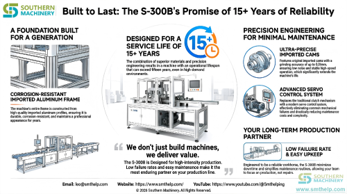
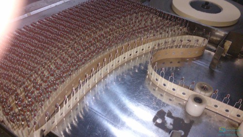
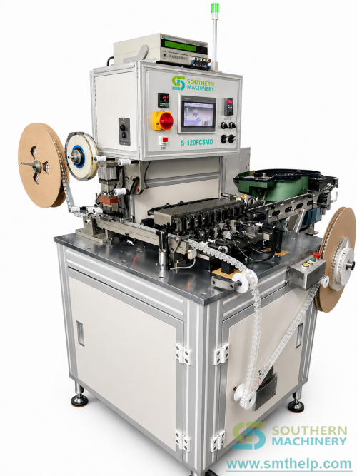
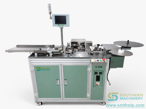
S-300BSTD radial component moulding and taping machine with the bulk bowl at the right and the forming line across the topBuilt to Last: the S-300B is specified for a 15+ year service life, with precision engineering for minimal maintenanceComponent families the machine tapes: switches, LEDs, capacitors, triodes, thermistors and connectorsRadial electrolytic capacitors already seated on paper tape, the output of the taping processDownstream step: automated THT radial insertion consuming tape-packaged radial leads
180 ± 20
components taped per minute
Ф4 – Ф10 mm
component diameter, two fixture sets
0.01 mm
cam grinding accuracy, imported cams
15+ years
designed mechanical service life
Founded in Shenzhen, 2011Radial forming, taping and insertion for THT linesDocuments, drawings and videos published without a form in front of them
The bottleneck

Your inserter is only as fast as the tape you hand it

A radial inserter does not care how careful your operators are. It cares that every part arrives the right way up, at the right lead pitch, in the right pocket of the tape, every time. Hand taping turns that into a human judgement repeated thousands of times a shift - and a judgement repeated that often is a defect rate, not a skill.

01

Taping is the step nobody costed

Ask for the cycle time of a THT line and you will get insertion, wave soldering and test. Ask for the time it takes to hand-form and hand-tape radial parts and the room goes quiet. It is usually the only station where the output of the whole line is set by how many people you can stand next to a bench.

02

A polarity error that never reaches the tester

Insert a radial electrolytic capacitor the wrong way round and it will pass a simple continuity check. It fails weeks later, in the field, with the case split. Sorting polarity by eye on a bench puts that failure into your warranty numbers instead of your scrap bin.

03

Every reel you buy is a tape you did not control

Pre-taped components are convenient right up to the moment your inserter starts mis-picking, and then the argument is between your line and a supplier you cannot audit. Taping in-house moves the tape specification - pitch, hole diameter, taping height, polarity direction - inside your own process, where you can change it.

Process

Nine stations between the bulk bin and the sealed tape

The station list below follows the machine walkthrough on the shop floor and the supplier manual for this machine class. It describes the order parts travel in, not the physical layout of the cabinet.

S-300B on the shop floor: bulk bowl on the right, forming and taping line across the top, control panel at the rear left
S-300B control architecture: PLC or MCU core, touch interface, real-time status monitoring and alarm display
01

Bulk feed

A vibratory bowl lifts loose components out of a bulk bin and orients them onto a linear track. A bowl eye stops the bowl when the track is full and a track eye slows the machine when the track runs short, so the machine tracks the feed rather than fighting it.

02

Lead spread

A spreader opens the two leads apart before anything else touches the body. Doing this first is what keeps the die from closing on a crossed lead, and it is why the machine can run parts straight out of a bag with no pre-sorting.

03

Lead forming

An integrated moulding die presses the leads to the formed pitch - 2.5 mm, 3.5 mm or 5.0 mm as standard. The die is one piece, so a pitch change is a die change, and the die comes off with four screws.

04

Polarity test

The part is measured for polarity. For a radial electrolytic capacitor, an LED or a diode this is the difference between a board that works and a board that comes back, and it is checked before the part is committed to the tape.

05

Re-orientation

If the polarity is the wrong way round for the tape the machine is building, a re-orientation station turns the part rather than rejecting it. Both directions are selectable, so the tape can be built positive-lead-first or negative-lead-first to match what your inserter expects.

06

Value test

With the matching tester fitted, the machine reads capacitance and resistance and compares them with the window you set. This is the station that catches the mixed bag - a wrong value that would otherwise be taped, boxed and shipped as a good part.

07

Lead trim

Over-long leads are cut to length before taping. Parts within the standard lead range pass through untouched; long-lead parts are trimmed at the station so the finished tape height is uniform instead of varying with the incoming lead length.

08

Reject ejection

A gate holds open for a good part and drops a failed part into a chute. Rejects leave the machine through a tube into a scrap container, physically separated from the good stream, so a failed part cannot be re-introduced by a tired operator at the end of a shift.

09

Tape and pack

A punch makes the 12.7 mm sprocket holes, the heater activates the top tape, the pressure roller seats the leads, and the indexer advances the paper by one pitch. Output is boxed (ammo pack) or coiled on a reel.

Station names and order are taken from the machine walkthrough and from the supplier manual for this machine class. The walkthrough is a shop-floor demonstration, not a specification document: it is evidence for the sequence, not for any dimension or rate.

LOAD
TEST
TAPE
Schematic of the sequence only - not a layout drawing and not to scale
Build

Where the money goes inside the machine

Three things decide whether a taping machine is still running in year ten: what drives it, what the moving parts are made of, and whether you can still get the fixtures. All three are stated in the product sheet, and all three are visible in the machine photographs.

Source: S-300B product sheet, presentation deck and machine photographs
S-300B

Servo control instead of a clutch

The drive uses a servo control system in place of the traditional mechanical clutch. The clutch is the assembly that wears, slips and eventually seizes on this class of machine, and it is the single largest source of unplanned downtime. Removing it removes the failure mode, not just the symptom.

S-300B

Imported cams, ground to 0.01 mm

All cams are imported originals with a grinding accuracy of 0.01 mm. At 180 parts a minute the cam set is what determines whether the machine runs quietly or shakes itself apart: 0.01 mm is the difference between consistent lead forming and a die that closes a fraction early on every thousandth part.

S-300B

Special-material fixtures and an integrated die

The square-rack feeder, the precision fixtures and the moulding die are made of special materials on an accurate centre line. The die is integrated rather than assembled, so the forming dimensions stay true and the changeover is fast and does not damage the product. Two fixture sets cover Ф4-Ф6 and Ф8-Ф10.

Specification

Every published parameter, one column per document

Each row names the document the value was read from. Where two documents disagree both values are printed side by side - read the open points section before you quote a number.

Reproduced from the supplied documents, not re-typed from memory
Parameter S-300B product sheet S-300B presentation deck S-300B machine walkthrough DT-300BSTD supplier manual
Model codeS-300B Fully Automatic High-Speed Molding and Taping MachineS-300B Automatic Molding and Taping MachineS300B radial (LED) lead components taping machineDT-300BSTD 全自动成型编带机 - supplier model, same machine class
Machine functionAutomatic lead forming (moulding) and taping of radial lead components, with testing and sortingFully automatic high-speed moulding and taping of radial components, testing and sorting good from defectiveRadial and LED lead forming and tapingAutomatic forming and taping of radial lead components
Control systemSingle-chip microcomputer as the core control unitThe world's most stable brand PLC, or a single-chip control systemNot statedSingle-chip control system
Operator interfaceLiquid-crystal display for order placement, simulating the status of each control pointTouch-screen operation interfaceTouch screen visible in the walkthroughTouch screen with alarm display and parameter pages
Taping speed180 ± 20 PCS/minute180 ± 20 pieces per minute; speaker notes also quote up to 200 pieces per minuteNot stated120 - 180 PCS/minute normal operating speed
Component diameter - standardФ6 - Ф10 mmФ6 - Ф10 mm standard fixture configurationNot statedФ3 - Ф10 mm
Component diameter - fixture setsФ4 - Ф6 share one set of fixtures, Ф8 - Ф10 share another; conventional range Ф4 - Ф10Two fixture sets, one for Ф4-Ф6 and one for Ф8-Ф10; other sizes within Ф4-Ф10 to orderNot statedNot stated
Component lengthL = 5 - 30 mm5 mm to 30 mmNot stated5 - 30 mm
Formed lead pitch - standard2.5 mm, 3.5 mm, 5.0 mm2.5 mm, 3.5 mm, 5.0 mm2.5 mm lead shown being formed, 5.0 mm die described2.0 mm, 2.5 mm, 3.5 mm, 5.0 mm
Formed lead pitch - to order7.5 mm, 10 mm, 15 mm and above, ordered separately7.5 mm, 10 mm and 15 mm custom pitches can be orderedNot stated7.5 mm and above optional
Tape hole pitch12.7 mm standard; other hole pitches customised on request12.7 mm standardNot stated12.7 mm, with 15 mm optional
Tape hole diameter4.1 mm4.1 mmNot statedФ4 mm with a tolerance of plus 0.2 mm
Taping height (hole centre to component base)17 mm - 21 mm17 mm - 21 mmNot stated17 - 22 mm
Polarity selectionNot statedNot statedPositive lead or negative lead first, selectable; the machine re-orients the part to suitPositive lead first or negative lead first, two selectable modes
Packaging methodBoxed or coiledBoxed (ammo packing) and coiled (reel) packing methods both supportedNot statedBoxed as standard, coiled optional
Paper tapeNot statedNot statedNot stated18 mm wide, 0.38 mm or 0.47 mm thick, selected to the product
Top tape widthNot statedNot statedNot stated6 mm, 10 mm, 12 mm or 15 mm, selected to the product
Lead trimNot statedNot statedLeads beyond roughly 25 mm are trimmed at the cutting station before tapingA cutting station removes the excess where the lead is too long
Reject handlingGood and defective products sorted automatically when the tester is fittedDefective products sorted out automaticallyThe eject gate opens for a good part and drops a failed part into a scrap tubeThe eject gate closes for a good part and opens to reject a defective part
Drive systemServo control system replacing the traditional clutchServo control system replacing the traditional clutchNot statedServo control system replacing the traditional clutch
Cam accuracyAll cams imported, grinding accuracy 0.01 mmImported cams ground to 0.01 mm accuracyNot statedAll cams imported, grinding accuracy 0.01 mm
FrameSquare rack feeder, precision fixtures of special materials on an accurate centre lineNot statedAluminium profile frame with branded panels visible in the walkthroughImported aluminium profile frame, corrosion resistant
Power supply220 V / 50 Hz / 1.6 kW220 V / 50 Hz / 1.6 kWNot stated1 HP motor, 220/380 V, 50/60 Hz
Air pressure4 - 5 kg/cm²4 - 5 kg/cm²Not stated4 - 5 kg/cm²
Machine dimensions (L × W × H)2200 × 1200 × 1500 mm2200 × 1200 × 1500 mmNot statedNot stated
Machine weight700 - 900 kg700 - 900 kgNot statedNot stated

How to read this table

All 26 rows are reproduced from the supplied documents. Where a document does not state a parameter the row says Not stated rather than borrowing a value from another machine. Rows where two documents disagree are repeated in the open points table below, and the discrepancy is left standing rather than resolved.

Open points

Where the documents disagree

A specification table that quietly picks one of two numbers is worth less than one that shows both. Six parameters below do not agree across the supplied documents, or are stated in only one of them. Confirm each against the current drawing for your configuration before you order.

Status: open - shown as found, not averaged and not silently resolved
Parameter What the S-300B documents say What the other source says What the difference means Status
Model namingThe product sheet and the presentation deck both call the machine S-300B. The walkthrough video calls it S300B, without the hyphen.The image library also holds a machine photographed and labelled S-300BSTD, and the supplier manual supplied with the enquiry covers a DT-300BSTD.Four codes circulate for what is presented as one machine class. S-300B is the code the product sheet and the deck agree on, so it is the code used on this page. If your quotation names S-300BSTD, ask which of the two it is - they are not the same build.To be confirmed
Control system and operator interfaceThe product sheet describes a single-chip microcomputer as the core control unit, with a liquid-crystal display for order placement that simulates the status of each control point.The presentation deck describes the world's most stable brand PLC or a single-chip control system, with a touch-screen operation interface.One document describes a fixed LCD annunciator panel and the other a touch screen, and they do not describe the same hardware. The machine photographs show a colour touch panel. This matters at quotation time: a touch panel and an LCD annunciator are different spares, different training and different prices.To be confirmed
Taping speedThe product sheet states a production capacity of 180 ± 20 PCS/minute, which is a band from 160 to 200.The presentation deck repeats 180 ± 20 pieces per minute, and its speaker notes then say the machine processes up to 200 components per minute - the top of the band presented as the rate. The supplier manual for this class states 120 - 180 PCS/minute.Three different framings of the same machine. The band is what the product sheet publishes and what this page quotes. Plan capacity from the bottom of the band, not the top, and treat 200 as a best case rather than a rate.To be confirmed
Component diameter rangeThe product sheet gives the processed product diameter as Ф6 - Ф10 mm, and separately states that the machine handles a conventional range of Ф4 - Ф10 in which Ф4 - Ф6 share one set of fixtures.The presentation deck says the standard fixture configuration covers Ф6 - Ф10 mm, with other sizes within the Ф4 - Ф10 range available as custom options. The supplier manual for this class states Ф3 - Ф10 mm.The product sheet describes Ф4 - Ф6 as part of the conventional range with its own fixture set, while the deck describes that band as a custom option. If you run components below Ф6, confirm whether the Ф4 - Ф6 fixture set is a standard line item or an order - the answer changes both the lead time and the price.To be confirmed
Taping heightThe product sheet gives a taping height of 17 mm - 21 mm.The presentation deck repeats 17 mm - 21 mm. The supplier manual for this class states 17 - 22 mm.A 1 mm difference at the top of the range. Taping height is set against your inserter's pick height, so if your tape specification sits at 22 mm, ask for it in writing before the order rather than adjusting on site.To be confirmed
Packaging and formed lead pitchThe product sheet lists boxed and coiled packaging as equal alternatives, and gives the standard formed lead pitch as 2.5 mm, 3.5 mm and 5.0 mm, with 7.5 mm, 10 mm and 15 mm and above ordered separately.The presentation deck lists boxed (ammo packing) and coiled (reel) as both supported. The supplier manual for this class states boxed as standard with coiled optional, and prints an additional 2.0 mm pitch in the standard set.Two questions to settle in the quotation rather than in the factory: whether coiled output is included or an option on the configuration you are buying, and whether 2.0 mm is a standard die or a special. Neither document is wrong; they describe different configurations.To be confirmed

This page is not a quotation. Values are reproduced from the documents named in each row, and the current drawing for your configuration governs. The supplier manual column refers to the DT-300BSTD, a machine of the same class from a different supplier - it is printed because it is the only supplied document that documents the tape consumables and the station-level fault table, and it is never used here to assert an S-300B value on its own.

Throughput

What 180 components a minute is worth over a shift

The published band is 180 ± 20 components per minute. The table converts that band into volume per hour, per shift and per month, so the number you plan with is a number you chose rather than one you were given.

Arithmetic on the published 180 ± 20 PCS/minute band, at 100 percent availability
Taping speedComponents per hourComponents per 8-hour shiftComponents per month, 26 days
160 PCS/min (bottom of band)9,60076,8001,996,800
180 PCS/min (nominal)10,80086,4002,246,400
200 PCS/min (top of band)12,00096,0002,496,000

Derived arithmetic on the published band, not a measured production figure. Every column assumes the machine is taping for the whole period, which no machine does. Multiply by the share of the shift it is actually running after bowl refills, box or reel changes, die changes and stops. It counts taped components, not shipped boards, and it assumes the machine is fed and emptied throughout.

Options

What is configured, not just what is listed

A taping machine is only useful if the die, the fixtures and the tape all match the component you actually run. These are the items to settle with the order rather than after it.

Items the product sheet lists as standard or to order, plus the consumables the supplier manual documents

Moulding die for your formed pitch

2.5 mm, 3.5 mm and 5.0 mm dies are standard. 7.5 mm, 10 mm, 15 mm and above are ordered separately. A die change is a four-screw operation, so a plant running two pitches can hold both.

Second fixture set for the other diameter band

Ф4-Ф6 and Ф8-Ф10 each use their own fixture set. If your component mix spans both bands, order both sets with the machine instead of discovering the gap on the first changeover.

Coiled output instead of boxed

Boxed (ammo pack) is the standard output. Coiled on a reel is the configuration to specify if your inserter takes reels - see the open points table, because the two supplied documents treat it differently.

Capacitance and resistance tester

The testing and sorting function works when the matching tester is fitted. Without it the machine still forms and tapes; with it, the machine also rejects out-of-window parts before they reach the tape.

Non-standard tape hole pitch

12.7 mm is standard. Other hole pitches are customised on request, and 15 mm appears as an option in the supplier documentation for this class - confirm against your inserter's tape specification.

Bowl and track tooling for your component

The bowl and the linear track are tooled to the component body. Send the drawing and a sample of the part, because a bowl that runs a 6 mm electrolytic will not necessarily run a square MKT of the same diameter.

Commissioning

Six steps from your component list to a validated tape

The order of work matters more than the speed of it. Most taping-machine problems that get blamed on the machine are a tape specification that was never agreed before the die was cut.

STEP 1

Agree the tape specification

Before anything is built: lead pitch, polarity direction, taping height, hole pitch, paper width and thickness, top tape width, boxed or reeled. This single document decides the die, the fixtures and the consumables.

STEP 2

Confirm the component

Send the component drawing and a physical sample. Body diameter, body height, lead diameter, lead length and body shape all move the fixture and the bowl tooling.

STEP 3

Prepare the bench, power and air

220 V single phase at 1.6 kW, 4-5 kg/cm² of clean dry air, and a level floor for a machine in the 700-900 kg band. Allow access on all four sides - the bowl, the reject tube and the output end all need to be reachable.

STEP 4

Tune the bowl and the track

Bowl amplitude, track eye positions and the spreader are set against the real component, not against a drawing. This is the step where a bad sample shows up as a rate problem three weeks later.

STEP 5

Validate the first tape

Run a full tape, then measure it: pitch, taping height, polarity direction, hole positions, and pull the sample against the component drawing. Keep the measured tape as the reference for the life of the machine.

STEP 6

Hand over with a maintenance card

Operator training on the touch panel, the parameter pages and the alarm list, plus a written maintenance card with the lubrication points and the cam and eye inspection intervals for your own records.

220 V / 50 Hz / 1.6 kW 4 - 5 kg/cm² air 2200 × 1200 × 1500 mm footprint 700 - 900 kg Bowl, reject tube and output all need clearance Keep the first validated tape as the reference

Power, air, footprint and weight are the published figures from the product sheet and the deck. Floor loading, extraction and local electrical practice are site matters and are not covered by the supplied documents.

Payback

What hand taping costs you per year

Every figure in this calculator is yours, not ours: the machine never asserts a saving of its own. Enter your component count, your board volume, what you pay the people who tape today, and what you would pay for the machine, and read the payback period off the bottom.

Taping labour and payback

Machine speed is fixed at the published rate; everything else is yours to set

Machine capacity
— components / h
Labour hours released
— h / month
Labour cost released
— USD / year
Payback
—
This is arithmetic on your own inputs, not a quotation and not a measured result. It counts taping labour only: it does not price the floor space, the consumables, the maintenance, the reduced rework or the warranty failures that a polarity error causes. Those are real, and they are yours to add.
Video

Watch the taping step, then watch what it feeds

Six clips from the Southern Machinery channel: three show the taping and forming step itself, one shows cut-and-form, and two show the insertion machines that consume the tape. They are here so you can judge the process, not to stand in for a specification.

Articles

Eight things worth knowing before you buy a taping machine

Each article is written for the person who has to justify the spend, not for the person who has to operate the machine. They are long on purpose: the decisions that go wrong on a taping machine are decided long before the machine arrives.

ARTICLE 01Your THT line is not slow at insertion, it is slow at the bench before it

The station that sets your line rate is usually the one nobody has a cycle time for.

Body text is kept in English on every language version by design: these are technical articles, and a machine-translated technical article is worse than an English one.

Ask a production manager for the cycle time of a THT line and you will get a competent answer about insertion, wave soldering and test. Ask for the time it takes to hand-form and hand-tape the radial parts that feed it and the conversation changes shape. Nobody measured it, because it never appeared as a station on the line layout. It appeared as headcount.

That is the whole problem. Hand taping does not fail loudly. It absorbs whatever volume you throw at it by absorbing more people, and because the cost is spread across wages rather than capital it never shows up as a number anybody has to defend. The line rate is therefore set by a bench, and the bench is invisible in every report you have.

The way to make it visible is a three-line calculation. Take the number of radial components on one board, multiply by the boards you build in a month, and divide by the taping rate of one person. That gives you person-months. Multiply by the fully loaded monthly cost of that person - not the wage, the wage plus the contributions, the supervision and the space - and you have the annual cost of a station that does not appear on your layout.

Then do the same division at 180 components a minute and subtract. What is left is the labour the machine releases, and it is usually the smallest number in the comparison. The larger numbers are the ones the bench hides: the reels you bought because you could not tape fast enough, the rework on boards where a lead pitch was formed to the wrong gauge, and the warranty claims on reversed electrolytics that passed every check you ran in-house.

The reason this matters beyond the first year is that the calculation repeats. Component counts per board go up as designs add decoupling and bulk capacitance. Volumes move up and down with demand. Every time either changes, a bench absorbs it by hiring, and a machine absorbs it by running. One of those two scales and the other one accumulates.

If you want the arithmetic done with your own numbers rather than a generic example, the calculator on this page takes the component count, the board volume, the taping rate and the wage, and returns the hours released and the payback period. It is worth five minutes before the next headcount review, if only to find out whether the bench is as cheap as it feels.

ARTICLE 02The polarity mistake that reaches the customer, not the tester

Why a reversed electrolytic capacitor passes every simple check you run in-house.

Body text is kept in English on every language version by design: these are technical articles, and a machine-translated technical article is worse than an English one.

Here is a failure that passes your end-of-line test, passes your functional test, passes a visual inspection under a lamp, and then splits its case open in a customer's enclosure six weeks after shipping. A radial electrolytic capacitor inserted with the polarity reversed will survive a surprising amount of testing before it dies, because the electrical continuity is perfect right up until the electrolyte vents.

The reason it survives is that a simple continuity or presence check cannot see polarity. It sees a component in a hole with two leads soldered. To see polarity you need a measurement that distinguishes anode from cathode, and that measurement has to happen before the part is committed - not after it is soldered into a board you cannot un-build.

There are two places to put that measurement. The first is at the inserter, and it is expensive: an insertion machine that verifies polarity is a more complex machine, and by the time the part reaches it the cost of the tape has already been paid. The second is at the taping machine, one step earlier, where a reversed part can still be turned rather than rejected.

That second option is the one worth designing for. A taping machine with a polarity station measures each part, and if the orientation is wrong for the tape being built, a re-orientation station rotates the part instead of throwing it away. Both directions are selectable, so the tape can be built positive-lead-first or negative-lead-first to match what the inserter expects. The consequence is that the failure mode is removed rather than detected.

The part that makes it durable is that the check happens on 100 percent of parts, at a rate of 180 a minute, without a person making a judgement. A human sorting by eye does the same job well for the first hour and less well after that, and the parts that slip through in hour nine are the ones that come back in month three. Consistency is the whole value of putting the check in the machine.

If you are currently sorting polarity by hand, the first useful thing to do is measure how often it goes wrong - put a counter on it for a week. If the answer is never, you have a good process and this is not your problem. If the answer is not never, the cost of that failure is already in your warranty numbers, and it is worth comparing it against putting the check one step earlier.

ARTICLE 03How to size a radial taping machine from a component list

Diameter, body height, lead diameter and lead length decide the machine, not the model number.

Body text is kept in English on every language version by design: these are technical articles, and a machine-translated technical article is worse than an English one.

The most expensive mistake in buying a taping machine is buying it by model number. Two machines with the same name and the same published speed can be unable to run the same component, because the parts that decide it - the bowl tooling, the track eyes, the spreader and the moulding die - are all cut for a specific body.

So the sizing conversation is a drawing conversation, not a catalogue conversation. Five numbers decide almost everything: body diameter, body height, lead diameter, lead length and the body shape. A 10 mm round electrolytic and a 10 mm square MKT of the same nominal diameter need different bowls, because a bowl that orients one will jam on the other.

Start with diameter, because it selects the fixture set. The published configuration covers Ф6 to Ф10 mm as standard, and the product sheet separately describes a conventional range of Ф4 to Ф10 mm in which Ф4-Ф6 share one fixture set and Ф8-Ф10 share another. If your component mix straddles both bands, you need both sets, and it is cheaper to order them with the machine than to discover it at the first changeover.

Then lead length, because it selects the forming die and the trim station. The machine handles product lengths of 5 to 30 mm and standard formed pitches of 2.5, 3.5 and 5.0 mm, with 7.5, 10, 15 mm and above to order. Parts with leads longer than the standard range are trimmed at the cutting station before taping, which is what keeps the finished tape height uniform rather than varying with whatever came out of the bag.

The number people forget is the tape specification. Taping height, hole pitch, hole diameter, paper width and thickness, top tape width and polarity direction are all set on the machine, and they are all things your inserter has an opinion about. Agreeing them in writing before the die is cut is what turns a machine purchase into a tooling project with a known end date.

The practical version of all this: send a component drawing and a physical sample, and ask for a written configuration that names the die, the fixture sets, the bowl tooling and the tape parameters. If the answer is a model number and a price, ask again - the parts that decide whether the machine works for you are not on the model number.

ARTICLE 04Boxed or reeled: the tape specification your inserter actually wants

Six numbers on a tape drawing that decide whether the inserter picks or mis-picks.

Body text is kept in English on every language version by design: these are technical articles, and a machine-translated technical article is worse than an English one.

A tape is a mechanical interface, and like every mechanical interface it has a tolerance. The number that catches people out is not the one on the tape drawing - it is the one that is missing from it, because the inserter's pick height and the taping machine's taping height have to agree and nobody wrote either of them down.

The visible failure is a mis-pick rate that creeps up. The inserter starts missing parts, or picks them at an angle, or clinches a lead that is not fully in the hole. The line blames the inserter. The inserter supplier blames the tape. Somebody measures a tape, finds the taping height is a millimetre off, and the argument ends - three weeks and a lot of goodwill later.

There are six numbers that decide whether a tape works. The sprocket hole pitch and diameter locate the tape against the feed wheel. The taping height sets where the component body sits relative to the hole. The paper width and thickness set how the tape behaves through the feed path. The top tape width sets the retention force that holds the leads down. And the polarity direction decides which way round every part arrives. Get those six agreed and the tape becomes a specification instead of a hope.

This is where building the tape in-house pays off in a way that is easy to miss. When you buy pre-taped components, those six numbers are decided by somebody else, and your only lever is to reject a batch and wait for another one. When you tape in-house, they are parameters on your machine that you can change, measure and freeze - and you can hold the measured first article as the reference for every tape you build afterwards.

That reference tape is the quiet part of the method. Tape one full strip, measure all six numbers, sign the measurement and keep the strip. Every subsequent batch is compared against a physical object rather than a memory. When something drifts - a punch wearing, a pressure roller flattening, a heater losing temperature - you find it by comparison instead of by a mis-pick rate three weeks downstream.

Before you order anything, get your inserter's tape specification in writing, or ask us for the blank form and fill it in with your process engineer. It takes an hour, it costs nothing, and it is the single document that decides whether the machine you buy is a working asset or an argument.

ARTICLE 05What 0.01 mm of cam accuracy is buying you at 180 parts a minute

The arithmetic that turns a grinding tolerance into a defect rate.

Body text is kept in English on every language version by design: these are technical articles, and a machine-translated technical article is worse than an English one.

0.01 mm sounds like a marketing number until you multiply it by 180 a minute. Then it becomes an arithmetic question: how many parts does a cam set touch in a year, and what does a fraction of a millimetre of accumulated error do to the parts it touches?

At 180 components a minute, a machine running two shifts touches roughly 170,000 parts a day. The cam set is what converts a continuous motor rotation into the discrete motions of forming, indexing and punching, and every one of those motions lands on a part. A cam ground to 0.01 mm holds its timing. A cam ground to a looser tolerance, or a cam that wears into a looser tolerance, starts closing the die a fraction early - not on every part, on the thousandth part, which is the worst possible failure rate because it survives your sampling.

The failure it produces is not a dramatic one. It is a lead formed to 2.48 mm instead of 2.50 mm, which still goes into the tape and still goes into the inserter and still goes into the hole, until it does not. Then you have a defect rate that nobody can reproduce on demand and a forming station that everybody suspects but nobody can prove wrong.

This is the argument for an imported cam set ground to 0.01 mm, and it is also the argument against a mechanical clutch. The clutch is the assembly that slips under load, wears at the engagement faces and eventually seizes - and when it slips, it does so intermittently, which puts a random timing error into the same station that the cam tolerance was there to protect. Replacing the clutch with a servo control system removes the largest source of intermittent timing error on the machine.

The practical consequence for the buyer is that these two features should be checked together, not separately. A precision cam set behind a slipping clutch is money spent and thrown away. A servo drive in front of a loose cam set is a fast machine with a variable output. What you want is both, and both are stated on the S-300B product sheet: servo control replacing the traditional clutch, and imported cams with a grinding accuracy of 0.01 mm.

The way to test the claim on your own parts is to measure a formed lead from the first hour of a shift and another from the ninth, and compare them with a micrometer rather than a go/no-go gauge. If they agree, the timing is holding. If they do not, you have found the defect source before it found your customer.

ARTICLE 06Running a taping machine for fifteen years: what actually decides it

Three assemblies fail before the frame does, and all three are replaceable by design.

Body text is kept in English on every language version by design: these are technical articles, and a machine-translated technical article is worse than an English one.

A taping machine does not die of old age. It dies of three specific assemblies, in a predictable order, and every one of them is replaceable. Knowing which three tells you whether a fifteen-year service life is a claim or a plan.

The first to go is the drive. On a conventional machine that means the clutch, which is a wearing assembly by design - it engages by friction, so it wears by definition, and the wear is progressive and intermittent. The symptom is a machine that starts missing index positions, then starts forming leads inconsistently, then stops. A servo control system replaces that entire failure mode rather than managing it.

The second is the punch and the pressure roller - the parts that touch the tape. They are consumables on any taping machine regardless of make, and the reason they matter is not their cost but their availability. A machine that needs a punch you cannot buy is a machine that is down for however long it takes to have one made. The supplier manual for this machine class lists the punch, the roller, the tape guides, the eyes and the heater as the consumable set, which means they can be stocked rather than improvised.

The third is the cam set, and this is where the fifteen-year figure is actually decided. Cams wear slowly, and a worn cam does not stop the machine - it degrades it, by a fraction of a millimetre, until the forming tolerance is outside the window and the defect rate becomes visible. The published figure is imported cams ground to 0.01 mm, which sets both the starting accuracy and the working life of the station.

What makes the difference between a machine that lasts fifteen years and one that is replaced in six is therefore not the frame. It is whether the wearing parts are designed to be replaced, whether the supplier still sells them, and whether the machine has a maintenance card that tells you when to look. A machine with a documented consumable list and a lubrication and inspection schedule will outlast a heavier machine with neither.

The concrete thing to ask for is the maintenance card and the consumable list, before you buy - not after. If a supplier cannot tell you which parts wear and where to get them, the fifteen-year figure is about the cabinet, not about the machine. On this class of machine the card covers lubrication points, the cam inspection interval and the eye inspection interval, and it takes an hour a month to keep.

ARTICLE 07The cost of a taped component is not the price of the tape

Where the money in hand taping really sits, and how to put a number on it.

Body text is kept in English on every language version by design: these are technical articles, and a machine-translated technical article is worse than an English one.

The price of a taped component is not the price of the tape. Tape is cheap - paper, adhesive and a sprocket hole. What you are buying when you buy a pre-taped part is somebody else's labour, somebody else's yield loss, somebody else's floor space and somebody else's margin, and none of those appear on the line item.

So the useful question is not what a taped part costs, it is what taping costs you today. And the answer has four parts. There is the labour: the people standing at the bench, at their fully loaded cost, for the hours they are there. There is the material: the reels you buy because you could not tape fast enough, which carry their own price and their own lead time. There is the yield: the parts damaged in hand-forming, and the boards that come back because a polarity error got through. And there is the space: a bench, a bin store and a staging area that are not making anything else.

Three of those four can be measured directly. Labour is a headcount and a wage. Material is an invoice. Space is a rent figure per square metre. Yield is harder, and it is the one that usually decides the case - because a reversed electrolytic that reaches a customer costs the return, the freight, the investigation and the goodwill, and it never appears in a taping cost analysis until somebody adds it up.

The method that makes the case defensible is to compute labour and material first, because those numbers are uncontroversial and they set a floor. If the labour released alone pays the machine back inside a period your finance team accepts, the argument is over and the yield improvement is a bonus. If it does not, the yield and warranty numbers have to carry the rest, and those need evidence rather than an estimate - which is why counting polarity failures for a week before the purchase is worth more than any savings model.

What makes this calculation stay true is that it is built on inputs you control and can revise. Component count per board changes. Volume changes. Wage rates change. A model built in a spreadsheet with your own numbers can be re-run every year, and the answer will move honestly with the business. A model built on a supplier's assumed saving cannot, which is why the calculator on this page takes your figures and asserts nothing of its own.

Put the four numbers in and read the payback period. If it is inside your capital threshold on labour alone, the decision is straightforward. If it is not, you now know exactly how much of the case rests on the yield argument - which is the honest position to walk into a budget meeting with.

ARTICLE 08Bringing tape in-house without bringing the quality problems with it

The verification routine that makes in-house taping an improvement rather than a risk.

Body text is kept in English on every language version by design: these are technical articles, and a machine-translated technical article is worse than an English one.

Bringing taping in-house is a quality decision disguised as a cost decision. The saving is real, but it only materialises if the tape you build in-house is at least as consistent as the tape you were buying - and consistency is a routine, not a machine.

The failure pattern is well known. A plant buys a taping machine, runs it well for three months, and then the mis-pick rate on the inserter starts to drift. Nobody can find a defect, because there is no defect - there is a slow change. A punch has worn by a few hundredths. A pressure roller has flattened. The heater is running slightly cooler and the adhesive is holding slightly less. Individually none of these is out of specification. Together they produce a tape that is subtly different from the tape that worked.

The routine that prevents it is a first-article comparison, and it has three parts. First, after commissioning, build one full tape and measure every parameter on it: formed pitch, taping height, hole positions, polarity direction, lead retention. Second, keep that tape and its measurement sheet as the reference, physically, in a bag with a date on it. Third, on a fixed interval - monthly is usually enough - build another tape and measure it the same way, against the reference rather than against the specification.

The difference between measuring against the reference and measuring against the specification is the whole point. Specification limits are wide enough to let a machine drift from one edge to the other without ever being out of tolerance, and it is that drift, not a violation, that changes the inserter's behaviour. A physical reference tape catches drift at the point where it starts.

What makes this durable is that the maintenance card and the reference tape reinforce each other. The card tells you when to look at the cams and the eyes; the reference tape tells you what the machine looked like when it was right. A plant with both has a process it can defend. A plant with neither has a machine and an opinion.

If you are about to bring taping in-house, the cheapest thing you can do is decide the measurement routine before the machine arrives: who measures, how often, with what, and where the reference tape is kept. It takes an afternoon to write down, and it is the difference between an improvement you can prove and one you can only assert.

Documents

Download the documents this page was written from

Everything quoted above is in the files below. Open them, check the numbers, and quote us the line you disagree with.

S-300B product sheet

The primary source for every parameter on this page: the 4-page Southern Machinery sheet for the S-300B fully automatic high-speed moulding and taping machine.

Radial taping process manuals

Manuals for two machines that work either side of taping: the SM-301 taped radial capacitor lead cutter and the S-C45 auto taped radial lead cutting machine.

Related forming and taping product sheets

The rest of the radial and axial forming and taping family, for plants running more than one component shape.

Radial taped feeder drawings

3D drawings of the radial taped feeders that consume the output of this machine, in the spans and bends used on SMT mounters.

Support

What happens after the machine lands

A taping machine is a tooling project as much as a machine purchase. These are the four parts of the service that decide whether it stays running.

✓

Die and fixture supply for the life of the machine

Moulding dies and fixture sets are supplied as line items, not as a favour. Order the second pitch with the machine and the changeover stays a four-screw job instead of a project.

⚑

Remote commissioning on your components

Send the component drawing and a sample before the machine ships. Bowl tooling, track eyes and the spreader are set against the real part, and the first tape is validated against your tape specification.

⚙

Operator and maintenance training

Training on the touch panel, the parameter pages, the alarm list, the lubrication points and the cam and eye inspection intervals, with a written maintenance card to keep.

Spares for the parts that actually wear

Punches, pressure rollers, tape guides, eyes and heater elements are the consumable set on this class of machine. They are listed so you can stock them rather than wait for them.

Questions

The questions we actually get asked

What components can the S-300B tape?
Radial lead components: electrolytic capacitors, MKT and metallized capacitors, LEDs, triodes, toggle switches, inductors, crystal oscillators, PTC thermistors, connectors, rubber sleeves and other pin-type parts. The standard fixture configuration covers bodies from Ф6 to Ф10 mm with a length of 5 to 30 mm; the product sheet also describes a conventional range of Ф4 to Ф10 mm using two fixture sets. Send the drawing if your part is outside that, because the bowl and the fixture are tooled to the body.
Does it test the components or only tape them?
Both, if the matching tester is fitted. The machine tests polarity on every part, and with the tester installed it also reads capacitance and resistance and compares them with the window you set. Parts outside the window are ejected into a scrap tube rather than taped. Without the tester the machine still forms and tapes; it simply stops rejecting on value.
Can it run both boxed and reeled output?
The product sheet lists boxed and coiled as equal alternatives and the presentation deck says both are supported. The supplier manual for this machine class describes boxed as standard with coiled optional. Because the two documents differ, this page lists it as an open point: tell us which output your inserter takes and we will confirm it on the quotation rather than leave you to find out on site.
What tape and paper does it use?
Paper tape 18 mm wide, in 0.38 mm or 0.47 mm thickness, with a top tape of 6, 10, 12 or 15 mm selected to the product, and a sprocket hole pitch of 12.7 mm with a 4.1 mm hole. Those consumable figures come from the supplier manual for this machine class, which is the only supplied document that prints them - so confirm them against your tape specification before ordering consumables in volume.
How fast is it, really?
The published band is 180 ± 20 components per minute, which is 160 to 200. Plan on the bottom of the band and treat 200 as a best case. The throughput table on this page converts that band into components per hour, per shift and per month, and it assumes the machine runs for the whole period - multiply by your own availability before you plan with it.
How long does a lead pitch change take?
The moulding die is integrated and comes off with four screws, and the product sheet describes rapid disassembly and assembly as a design feature. A pitch change is therefore a die change, not a re-setup. What takes longer is the first-article validation - measure the first tape against your tape specification before releasing the machine to production.
What does the machine need on site?
220 V single phase at 1.6 kW, clean dry air at 4 to 5 kg/cm², and a level floor for a machine weighing 700 to 900 kg with a footprint of 2200 × 1200 × 1500 mm. Leave access on all four sides: the bulk bowl, the reject tube and the output end all need to be reachable during a shift.
How do I get a quotation?
Send the component drawing or part number, the tape specification your inserter uses, and your monthly component volume. With those three we can name the die, the fixture sets, the bowl tooling and the output configuration on the quotation instead of listing options and leaving you to guess. If you do not have a tape specification yet, say so - we will send the blank form.
Contact

Send us the component and we will send back a configuration

The useful enquiry is short: what the part is, what tape your inserter takes, and how many you run a month. Everything else we can work out with you.

S-300B radial lead moulding and taping machine enquiry

This form opens your own mail client. Nothing is sent to a server from this page.

Send one component and one tape drawing

With a component sample and your tape specification we can confirm the die, the fixture sets and the output configuration in writing, before you commit to anything.

Request a component trial